The Floppy Disk Controller
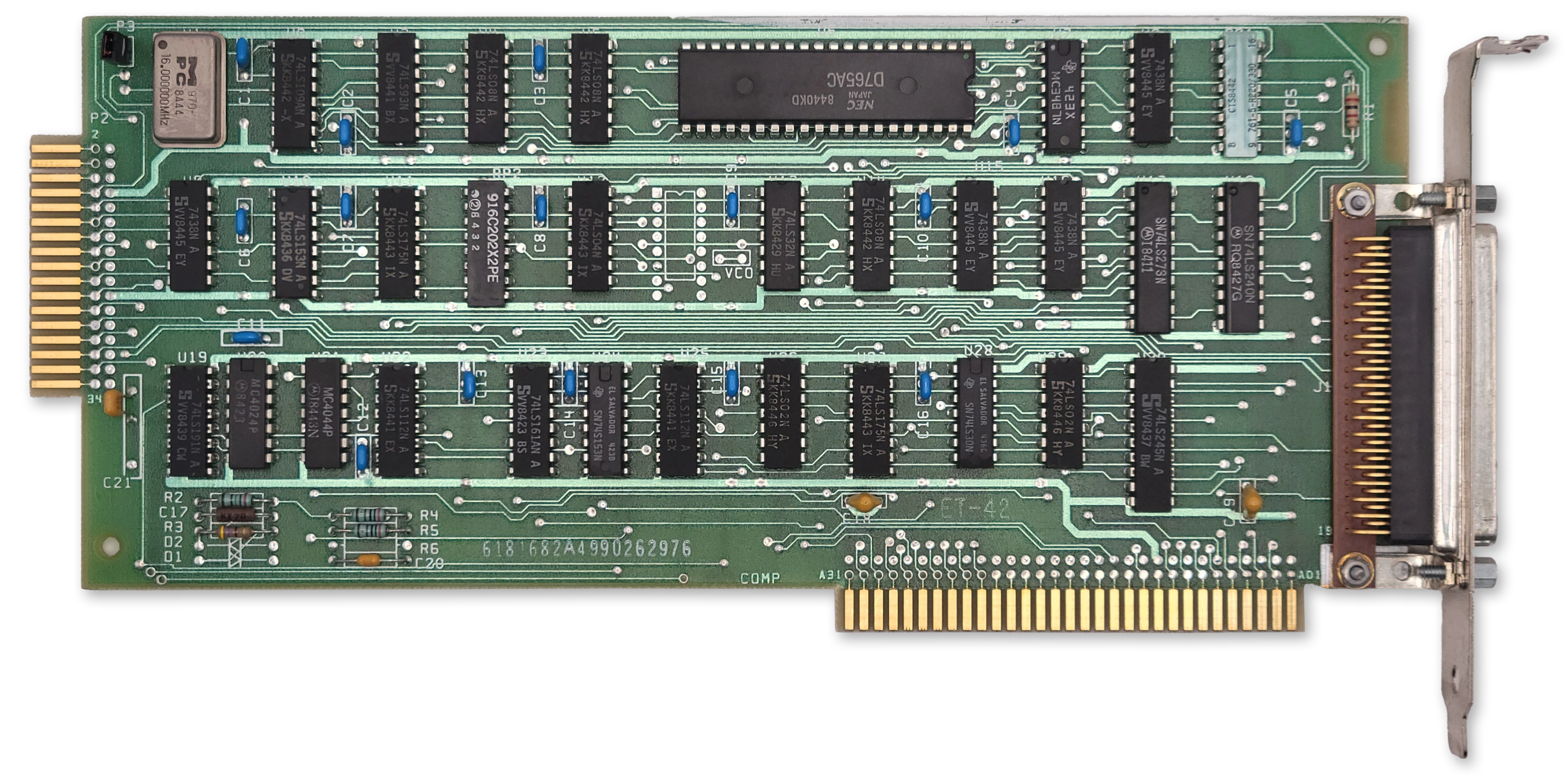
The IBM 5.25" Diskette Drive Adapter
IBM PC/XT systems outfitted with a floppy disk drive had an IBM 5.25“ Diskette Drive Adapter card installed in one of the available expansion slots.
At a Glance
| Item | Description |
|---|---|
| Controller IC | NEC µPD765A or Intel P8272A |
| Adapter clock | 16.0MHz crystal; 8MHz controller clock |
| Supported drives | Up to 4 |
| DMA Channel | Channel 2 |
| Interrupt | IRQ6 |
| Primary I/O range | 3F0h-3F7h |
| Secondary I/O range | 370h-377h |
| DOR | 3F2h primary, 372h secondary |
| Main status register | 3F4h primary, 374h secondary |
| Data register | 3F5h primary, 375h secondary |
| Expansion ROM | None |
Controller Overview
The IBM floppy drive controller, as we’ll refer to it here, was a collection of 74-series logic chips and a 16.0MHz clock crystal supporting the “brain” of the card, a NEC µPD765A (NEC 765) floppy drive controller chip (or the more-or-less identical Intel P8272A).
Note
Microscope photography of the Intel P8272A has revealed the numbers ‘765’ are present on the die, implying Intel licensed NEC’s design and the controllers can be considered basically identical.
The IBM floppy controller could support up to four floppy disk drives, although configurations of more than two were uncommon. Drives 0-3 would be assigned the drive letters A-D up until MS-DOS 5.0, whereupon DOS started to reserve drive letter C for hard disks. It might feel a bit cursed to have a floppy disk as drive C, but if you did indeed have three drives connected and an earlier version of MS-DOS, that’s what you’d end up with.
The NEC 765 takes an 8MHz clock, divided once from the card’s 16MHz crystal. It has a maximum data rate of 250kbps, limiting it to support of double-density diskettes only.
The 765 doesn’t perform every function needed by a floppy controller. Notably, the controller’s voltage-controlled oscillator (VCO), a crucial part of the controller’s phase-locked-loop (PLL) is external to the 765, although the 765 has pins for interacting with it. Also external to the 765 is the data separator circuitry.
Operation
On the IBM PC/XT, the floppy drive controller is operated by the BIOS in DMA mode exclusively. It is possible to operate the controller in polled-io mode (PIO) in a manual fashion, but there are severe disadvantages to doing so - as was seen on the IBM PCjr which lacked a DMA controller. The lack of DMA prevented such operations as transferring data via the serial ports and floppy disk drive at the same time.
The 765 operates as a state machine with three basic operational phases:
- During the command phase the controller receives bytes from the host that instruct it to perform a specific operation.
- During the execution phase the controller carries out the operation specified in the command phase.
- During the result phase the controller provides status information to the host describing the result of the execution phase.
The 765 is capable of running some operations such as Seek and Recalibrate on multiple drives simultaneously.
The 765 maintains an internal register holding the current cylinder, called the Present Cylinder Number (PCN), for each of the four supported disk drives.
I/O Ports
The IBM Diskette Drive Adapter decodes the following I/O port addresses:
| Primary | Secondary | 765 Port | RW | Description |
|---|---|---|---|---|
3F0h | 370h | n/a | Base Address | |
3F2h | 372h | n/a | W | Digital Output Register |
3F4h | 374h | 0 | R | µPD765A Status Register |
3F5h | 375h | 1 | RW | µPD765A Data Register |
Floppy Controller Cable Pinout
The IBM floppy controller has two connectors, an internal and external connector, each supporting two drives. The external connector will not be discussed here as it was rarely used.
The internal connector is of the edge connector type, and contains 34 contacts. Other floppy controllers may have a 34-pin, double-row male header.
All of the odd pins of the connector — one entire side — consist of ground connections. That leaves the other side with the following pinout:
| Pin | I/O | Purpose |
|---|---|---|
| 2 | Unused | |
| 4 | Unused | |
| 6 | Unused | |
| 8 | Input | |
| 10 | Output | Motor Enable A |
| 12 | Output | Drive Select B |
| 14 | Output | Drive Select A |
| 16 | Output | Motor Enable B |
| 18 | Output | |
| 20 | Output | |
| 22 | Output | |
| 24 | Output | |
| 26 | Input | |
| 28 | Input | |
| 30 | Input | |
| 32 | Output | |
| 34 | Unused |
IBM floppy drive cables famously have a twist that reverses conductors 10—16. This allows every drive used in an IBM PC to be configured as drive 1 (DS1). This means that the drive desired to be the first floppy drive (A) should be at the end of the floppy cable.
Floppy Drive Communication
The electrical interface to a floppy drive is rather simple in concept. The controller manipulates the drive select and motor lines to activate the desired floppy drive and spin its motor up to its operating RPM. While rotating, regular, active-low pulses of the signal occur as the floppy drive’s index sensor detects the index hole. As the drive detects flux transitions, active-low pulses of the signal occur. If the controller wishes to write data, it will assert and then provide the appropriate pulses on the .
The controller specifies which head should be active via the output. If this signal is asserted, then head 1 is specified for all operations.
The controller can detect when the drive is positioned at the outermost track, track 0, via an active-low signal.
The Digital Output Register
The IBM controller card adds a main control register external to the 765, called the Digital Output Register or DOR. The DOR has several functions — it selects a specific drive as the target of operations, it can reset the 765, it can enable or disable interrupts and DMA, and it can turn on and off the attached floppy drive motors.
The DOR is a write-only register implemented with a 74LS273 8-bit register chip.
| Bits | Name | Description |
|---|---|---|
| 0:1 | DR | DR: Selected drive |
| 2 | RESET | Controller reset gate 0: Hold controller in reset 1: Enable controller |
| 3 | DMA | DMA and interrupt request enable 0: Disable DMA/IRQ 1: Enable DMA/IRQ |
| 4 | MOTA | Drive A motor control 0: Motor off 1: Motor on |
| 5 | MOTB | Drive B motor control 0: Motor off 1: Motor on |
| 6 | MOTC | Drive C motor control 0: Motor off 1: Motor on |
| 7 | MOTD | Drive D motor control. 0: Motor off 1: Motor on |
DR: Selected drive
| DR1 | DR0 | Drive |
|---|---|---|
| 0 | 0 | 0 (A) |
| 0 | 1 | 1 (B) |
| 1 | 0 | 2 (C/D) |
| 1 | 1 | 3 (D/E) |
Drive Selection Bits
The two least significant bits (Bits 0—1) of the DOR control which floppy drive is selected.
Important
If a drive’s motor is not on, selecting it in the DOR will do nothing until the motor is turned on.
To avoid confusion, be aware that the DOR is the only drive selection method used by the IBM floppy drive controller. The NEC 765 command set includes fields that select which drive the operation is intended to target. Under IBM’s controller design, these bits do nothing externally — the 765 is not in control of which drive is selected. You can verify this yourself by noting the 765’s unit select pins, 28 and 29, are not connected on the schematic.
Important
Even though the 765 does not control drive selection, a programmer should ensure that the drive selected in the DOR matches the drive number specified in commands. A mismatch in the drive selected in the DOR and command phase can cause incorrect operation of the Seek and Recalibrate commands.
Reset Bit
The DOR’s bit 2 drives the 765’s active-high RST pin (1) via an inverter. When a 1 is written to bit 2, the 765’s RST pin is pulled low, holding the controller in reset.
Note
The IBM floppy controller card ties the 765’s RDY pin (35) high. This causes the 765 to generate an interrupt after coming out of the RESET state after “1-25ms”, according to the datasheet. The controller is reset quite often during normal operation.
The 765 Registers
The 765 contains five status registers in total. The first of these is the main status register (MSR). The MSR is the only status register that may be read at any time. The contents of the other status registers, ST0—ST3, are sent to host during the controller result phase.
The Main Status Register
| Bits | Name | Description |
|---|---|---|
| 0 | D0B | Drive 0 (A) is performing a seek or recalibrate operation |
| 1 | D1B | Drive 1 (B) is performing a seek or recalibrate operation |
| 2 | D2B | Drive 2 (C) is performing a seek or recalibrate operation |
| 3 | D3B | Drive 3 (D) is performing a seek or recalibrate operation |
| 4 | BUSY | Controller is busy |
| 5 | NDMA | Non-DMA execution mode indicator 0: Controller in DMA mode 1: Controller in PIO (Non-DMA mode) |
| 6 | DIO | Data Input/Output Direction 0: Host to controller 1: Controller to host |
| 7 | MRQ | Main Request 0: The controller is not expecting to send or receive data 1: The controller has data to send to the CPU, or is ready to receive the next byte of data |
The BUSY bit
The BUSY bit is set when the controller is executing a command, and is only cleared when the last byte of the result phase has been read by the host CPU. It can be used as a general indication that a new command should not be sent to the CPU.
The DIO bit
The DIO bit controls the direction of transfer to or from the controller. The CPU should only send data to the controller when DIO is 0. When DIO is 1, the controller is not ready to receive data — it expects to have data to send to the CPU.
The MRQ bit
The MRQ bit can be usefully combined with the DIO bit to control data transfer to and from the controller.
| DIO | MRQ | Meaning |
|---|---|---|
| 0 | 0 | FDC is not ready to receive a byte from the CPU. (Busy, reset/disabled, or DMA operation in progress) |
| 0 | 1 | FDC is ready and expecting to receive a command or data byte from the CPU via the data register. |
| 1 | 0 | FDC has data pending, but not yet ready to read. |
| 1 | 1 | FDC has a byte ready for the CPU to read from the data register. Result bytes, sense bytes, or PIO read data. |
Note
This bit may also be labelled as
RQMin technical references.
Status Register 0 (ST0)
| Bits | Name | Description |
|---|---|---|
| 0:1 | US | US: Unit select |
| 2 | HD | Currently active drive head |
| 3 | NR | Drive not ready |
| 4 | EC | Equipment check 0: No fault detected. 1: The target drive reports a fault, or track 0 sensor may be inoperable |
| 5 | SE | Seek end 0: No seek performed. 1: The controller successfully executed a seek or recalibrate operation. This includes commands with an implicit seek. |
| 6:7 | IC | IC: Interrupt code |
US: Unit select
| US1 | US0 | Drive |
|---|---|---|
| 0 | 0 | 0 (A) |
| 0 | 1 | 1 (B) |
| 1 | 0 | 2 (C/D) |
| 1 | 1 | 3 (D/E) |
IC: Interrupt code
| IC1 | IC0 | Meaning |
|---|---|---|
| 0 | 0 | Normal termination |
| 0 | 1 | Abnormal termination The controller encountered an error condition during the execution phase. |
| 1 | 0 | Invalid command |
| 1 | 1 | Polling status change A drive became ready or became not-ready during a drive poll. |
Note
The IBM floppy controller does not connect the typical floppy drive indication line, pin 34. Therefore the NR bit will typically not be set, even if the drive door is open and/or no disk is inserted into the drive. If you emulate this bit anyway, you may receive a “General Failure” error message in DOS when no disk is inserted instead of the expected “Not Ready Reading Drive” error.
Correspondingly, since a drive cannot report not-ready during the execution phase, an IC code of
11bwill not be encountered.
Note
The IBM floppy controller does not accommodate an external fault signal, nor do most PC floppy drives supply one. Therefore the EC field can only report failure of the Track 0 sensor during a Seek or Recalibrate operation.
Status Register 1 (ST1)
| Bits | Name | Description |
|---|---|---|
| 0 | MA | Missing ID address mark. |
| 1 | NW | Not writable 1: A write operation was attempted, but the drive reported the media is write-protected. |
| 2 | ND | No Data 1: A required sector ID was not found during the execution phase. |
| 3 | Unused | Unused, always 0 |
| 4 | OR | Overrun/Timeout 1: The controller was not serviced within the required time window, and the operation has failed. |
| 5 | DE | Data error 1: The controller detected a bad CRC in either the sector address or data fields. |
| 6 | Unused | Unused, always 0 |
| 7 | EN | End of Cylinder 1: The controller attempted to access a sector beyond the last sector on a track. |
The No-Data Bit
The No-Data bit is set under the following conditions:
- The FDC could not find the requested sector during execution of
READ DATA,WRITE DELETED DATAorSCAN - The FDC could not read the ID field during execution of
READ ID - The FDC could not find the starting sector during execution of
READ CYLINDER.
Status Register 2 (ST2)
| Bits | Name | Description |
|---|---|---|
| 0 | MD | Missing Data 1: The FDC could not find a data address mark (DAM) or deleted data address mark (DDAM). |
| 1 | BC | Bad cylinder 1: A sector ID with a C of FF was encountered and not explicitly requested. |
| 2 | SN | Scan Not Satisfied 1: During execution of SCAN, no sector satisfying the scan condition could be located. |
| 3 | SH | Scan Equal Hit 1: The EQUAL condition was satisfied during execution of SCAN. |
| 4 | WC | Wrong cylinder 1: A sector ID was encountered specifying a C that does not match the requested C. |
| 5 | DD | Data Error In Data Field 1: The FDC encountered a bad data field CRC. |
| 6 | CM | Control Mark 1: During READ DATA or SCAN, a deleted data address mark (DDAM) was encountered, ORDuring READ DELETED DATA a normal data address mark (DAM) was encountered. |
| 7 | Unused | Unused |
Status Register 3 (ST3)
| Bits | Name | Description |
|---|---|---|
| 0:1 | US | US: Unit select The state of the 765’s unit select pins. |
| 2 | HD | Head address The side select signal from the floppy drive. |
| 3 | TS | Two-sided signal The two side signal from the floppy drive. |
| 4 | T0 | Track 0 The track 0 signal from the floppy drive. |
| 5 | RY | Drive ready The ready signal from the floppy drive. |
| 6 | WP | Write-protect status 1: The floppy drive reports the media is write-protected. |
| 7 | FT | Fault Signal 1: The floppy drive is in a fault condition. |
US: Unit select
| US1 | US0 | Drive |
|---|---|---|
| 0 | 0 | 0 (A) |
| 0 | 1 | 1 (B) |
| 1 | 0 | 2 (C/D) |
| 1 | 1 | 3 (D/E) |
Important
Remember that on the IBM floppy controller, the 765’s unit select pins are not connected and do not drive selection of floppy drives.
Controller Commands
The 765 supports 15 different commands:
| Code | Command Name | MT | MF | SK |
|---|---|---|---|---|
06h | Read Data | ✔️ | ✔️ | ✔️ |
0Ch | Read Deleted Data | ✔️ | ✔️ | ✔️ |
0Ah | Read ID | 0 | ✔️ | 0 |
02h | Read Track | 0 | ✔️ | ✔️ |
11h | Scan Equal | ✔️ | ✔️ | ✔️ |
19h | Scan Low or Equal | ✔️ | ✔️ | ✔️ |
1Dh | Scan High or Equal | ✔️ | ✔️ | ✔️ |
03h | Specify | 0 | 0 | 0 |
05h | Write Data | ✔️ | ✔️ | 0 |
09h | Write Deleted Data | ✔️ | ✔️ | 0 |
0Fh | Seek | 0 | 0 | 0 |
07h | Recalibrate | 0 | 0 | 0 |
0Dh | Format Track | 0 | ✔️ | 0 |
08h | Sense Interrupt Status | 0 | 0 | 0 |
04h | Sense Drive Status | 0 | 0 | 0 |
Commands consist of 2—9 command bytes, sent during the command phase. The command will then enter the execution phase. When complete (or on error) the command enters the result phase and various status register bytes will be made available to read out from the data register.
The first command code byte 0 is common to all commands and contains the command code as given in the table above, along with operational flags. These flags are not always applicable to each command. The flags applicable to each command are noted in the table above.
Command Code Byte 0
| Bits | Name | Description |
|---|---|---|
| 0:4 | Command | Five-bit command number |
| 5 | SK | Skip deleted data address marks |
| 6 | MF | MFM/FM mode select 1: MFM mode selected. 0: FM mode selected. |
| 7 | MT | Multi-track operation 1: Request multi-track operation 0: Normal operation |
Command Code Byte 1
| Bits | Name | Description |
|---|---|---|
| 0:1 | DR | DR: Drive select |
| 2 | HD | Head select |
| 3:7 | Reserved | Reserved |
DR: Drive select
| US1 | US0 | Drive |
|---|---|---|
| 0 | 0 | 0 (A) |
| 0 | 1 | 1 (B) |
| 1 | 0 | 2 (C/D) |
| 1 | 1 | 3 (D/E) |
Sector Size (N)
Many commands take a parameter N which represents the size of the sector to operate on. N is not the actual sector size, but can be used to calculate it by shifting 128 left by the value of N (ex: 128 << N).
The following values of N are valid:
| Value | Meaning |
|---|---|
| 0 | 128/DTL |
| 1 | 256 |
| 2 | 512 |
| 3 | 1024 |
| 4 | 2048 |
| 5 | 4096 |
| 6 | 8192 |
Note
The largest sector size supported by the 765 is N==6, or 8192 bytes. Some controllers support larger values of N, but this is already impractical as an 8192 byte sector will wrap completely around the track.
An N of 0 is special. This indicates a sector size of 128 bytes, but fewer than 128 bytes can be read from a sector with N == 0 via means of the DTL field.
Data Length (DTL) Field
When reading or writing most sectors with N > 0, the DTL field is not used, and should be set to FFh.
When reading or writing a sector with N == 0, the DTL field is honored, up to a maximum of 128 bytes. The entire sector is still read and written, to either validate the CRC in the case of reading, or to calculate and write the CRC in case of writing. In the write case, the unspecified bytes of the sector are padded with 00h.1
The Read Data Command
The Read Data command is opcode 06h.
The Read Data command searches for the sector ID matching the specified cylinder, head, sector and sector size. The matching sector must have a normal data address mark (DAM).
In DMA mode, it will read successive sectors that have a normal DAM until terminal count. In PIO mode, it will read successive sectors that have a normal DAM until EOT is reached.
If the MT flag is set, once the last sector of side 0 is transferred, the FDC proceeds to repeat the operation on side 1.
The Read Data command behaves as follows depending on the value of the SK flag:
| SK | DAM Type | Sector Read | CM | Result |
|---|---|---|---|---|
| 0 | Normal | Y | 0 | Normal Termination |
| 0 | Deleted | Y | 1 | No Further Sectors Read |
| 1 | Normal | Y | 0 | Normal Termination |
| 1 | Deleted | N | 1 | Sector Skipped |
After the data is transferred, the command enters the result phase.
Status Flags Affected
| Flag | Register | Triggering Event |
|---|---|---|
| WC | ST2 | Value of C mismatch in Sector ID |
| BC | ST2 | Value of C mismatch in Sector ID and C was 0xFF |
| CM | ST2 | A deleted data address mark (DDAM) was encountered |
| ND | ST1 | No matching Sector ID was found |
| MA | ST1 | No sector ID address mark (IDAM) was found within two index pulses |
| DE | ST1 | A bad data field CRC was encountered |
Command Format
| Phase | Byte | Byte |
|---|---|---|
| Command | 0 | Command Code Byte 0 |
| Command | 1 | Command Code Byte 1 |
| Command | 2 | Cylinder |
| Command | 3 | Head |
| Command | 4 | Sector |
| Command | 5 | Sector Size (N) |
| Command | 6 | End of Track |
| Command | 7 | Gap 3 Length |
| Command | 8 | Data Length (DTL) |
| Result | 0 | ST0 |
| Result | 1 | ST1 |
| Result | 2 | ST2 |
| Result | 3 | Cylinder |
| Result | 4 | Head |
| Result | 5 | Sector |
| Result | 6 | Sector Size (N) |
The Read Deleted Data Command
The Read Deleted Data command is opcode 0Ch.
The Read Deleted Data command searches for the sector ID matching the specified cylinder, head, sector and sector size. The matching sector must have a deleted data address mark (DDAM).
In DMA mode, it will read successive sectors that have a DDAM until terminal count. In PIO mode, it will read successive sectors that have a DDAM until EOT is reached.
If the MT flag is set, once the last sector of side 0 is transferred, the FDC proceeds to repeat the operation on side 1.
The Read Deleted Data command behaves as follows depending on the value of the SK flag:
| SK | DAM Type | Sector Read | CM | Result |
|---|---|---|---|---|
| 0 | Normal | Y | 1 | No Further Sectors Read |
| 0 | Deleted | Y | 0 | Normal Termination |
| 1 | Normal | N | 1 | Sector Skipped |
| 1 | Deleted | Y | 0 | Normal Termination |
After the data is transferred, the command enters the result phase.
Status Flags Affected
| Flag | Register | Triggering Event |
|---|---|---|
| WC | ST2 | Value of C mismatch in Sector ID |
| BC | ST2 | Value of C mismatch in Sector ID and C was 0xFF |
| CM | ST2 | A normal data address mark (DAM) was encountered |
| ND | ST1 | No matching Sector ID was found |
| MA | ST1 | No sector ID address mark (IDAM) was found within two index pulses |
| DE | ST1 | A bad data field CRC was encountered |
Command Format
| Phase | Byte | Byte |
|---|---|---|
| Command | 0 | Command Code Byte 0 |
| Command | 1 | Command Code Byte 1 |
| Command | 2 | Cylinder |
| Command | 3 | Head |
| Command | 4 | Sector |
| Command | 5 | Sector Size (N) |
| Command | 6 | End of Track |
| Command | 7 | Gap 3 Length |
| Command | 8 | Data Length (DTL) |
| Result | 0 | ST0 |
| Result | 1 | ST1 |
| Result | 2 | ST2 |
| Result | 3 | Cylinder |
| Result | 4 | Head |
| Result | 5 | Sector |
| Result | 6 | Sector Size (N) |
The Read ID Command
The Read ID command is opcode 0Ah.
The FDC returns the fields of the next Sector ID encountered on the track.
The MT and SK flags are not valid for this command and should be 0.
Status Flags Affected
| Flag | Register | Triggering Event |
|---|---|---|
| MA | ST1 | No sector ID address mark (IDAM) was found within two index pulses |
Command Format
| Phase | Byte | Byte |
|---|---|---|
| Command | 0 | Command Code Byte 0 |
| Command | 1 | Command Code Byte 1 |
| Result | 0 | ST0 |
| Result | 1 | ST1 |
| Result | 2 | ST2 |
| Result | 3 | Cylinder |
| Result | 4 | Head |
| Result | 5 | Sector |
| Result | 6 | Sector Size (N) |
The Read Track Command
The Read Track command is opcode 02h.
Unlike what its name might suggest, Read Track does not actually read a raw track. Instead, it reads all sectors on a track, regardless of ID or CRC validation.
The Read Track command first waits for the index signal. It then returns the data for each sector encountered, in order. The Sector ID of the first sector is checked against the values given to the command for the purposes of setting the ND bit in ST1, but a mismatch is not an error and does not stop command execution.
The MT and SK flags are not valid for this command and should be 0.
Status Flags Affected
| Flag | Register | Triggering Event |
|---|---|---|
| ND | ST1 | Sector ID comparison failed (command continues) |
| DD | ST2 | A bad data field CRC was encountered (command continues) |
| DE | ST1 | A bad field CRC was encountered (command continues) |
Command Format
| Phase | Byte | Byte |
|---|---|---|
| Command | 0 | Command Code Byte 0 |
| Command | 1 | Command Code Byte 1 |
| Result | 0 | ST0 |
| Result | 1 | ST1 |
| Result | 2 | ST2 |
| Result | 3 | Cylinder |
| Result | 4 | Head |
| Result | 5 | Sector |
| Result | 6 | Sector Size (N) |
The Scan Commands
The three scan commands, Scan Equal, Scan High or Equal, and Scan Low or Equal, behave identically other than the mathematical expression they evaluate for each pair of bytes processed.
In each of the three commands, the FDC performs a comparison (the scan condition) between bytes read from the disk and bytes provided by the host. If this comparison is true for the entire sector, the scan condition is said to have been satisfied or that a scan hit has occurred, at which point the scan operation will enter the result phase.
The value of FFh is special, and is treated as a wildcard. If either the byte from the disk or the byte from the host is FFh then the comparison will be considered true. This allows use of FFh by the host to mask the comparison bytes provided to the FDC.
If a sector does not satisfy the scan condition, the FDC will continue with the next sector to scan based on the STP step parameter. If STP == 1, this will be the next consecutive sector number. If STP == 2, then the FDC will skip the next consecutive sector number.
Important
Regardless of the STP parameter, the FDC must be able to read the last sector on the track as specified by EOT. Unexpectedly encountering the index pulse during the scan operation will result in abnormal termination.
If EOT is reached or terminal count occurs before a scan hit occurs, then the scan operation ends with a scan not satisfied condition. In the case of a terminal count, the operation ends after the current byte being compared.
Scan Command Operations
| Code | Command | Effective Operation |
|---|---|---|
11h | Scan Equal | (Byte from Disk) == (Byte from CPU) |
19h | Scan Low or Equal | (Byte From Disk) ≤ (Byte from CPU) |
1Dh | Scan High or Equal | (Byte From Disk) ≥ (Byte from CPU) |
Status Flags Affected
| Flag | Register | Triggering Event |
|---|---|---|
| OR | ST1 | An overrun condition occurred during the scan operation |
| SH | ST2 | The scan condition was satisfied (scan hit) |
| SN | ST2 | The scan condition was not satisfied |
| CM | ST2 | A deleted data address mark (DDAM) was encountered |
Command Format
| Phase | Byte | Byte |
|---|---|---|
| Command | 0 | Command Code Byte 0 |
| Command | 1 | Command Code Byte 1 |
| Command | 2 | Cylinder |
| Command | 3 | Head |
| Command | 4 | Sector |
| Command | 5 | Sector Size (N) |
| Command | 6 | End of Track |
| Command | 7 | Gap 3 Length |
| Command | 8 | Sector Step Size (STP) |
| Result | 0 | ST0 |
| Result | 1 | ST1 |
| Result | 2 | ST2 |
| Result | 3 | Cylinder |
| Result | 4 | Head |
| Result | 5 | Sector |
| Result | 6 | Sector Size (N) |
The Specify Command
The Specify command sets three timing variables for the drive as well as setting the FDC operational mode to DMA or PIO modes.
The Specify command has no result phase.
Command Format
| Phase | Byte | Byte |
|---|---|---|
| Command | 0 | Command Code Byte 0 |
| Command | 1 | Specify Timing 0 |
| Command | 2 | Specify Timing 1 |
Command Byte 1: Specify Timing 0
| Bits | Name | Description |
|---|---|---|
| 0:3 | HUT | Head unload time Time between end of execution phase and head unload, in units of 16 milliseconds |
| 4:7 | SRT | Step rate time Time between step pulses in milliseconds |
Command Byte 2: Specify Timing 1
| Bits | Name | Description |
|---|---|---|
| 0 | ND | Non-DMA Mode 0: DMA mode selected 1: Non-DMA (PIO) mode selected |
| 1:7 | HLT | Head Load Time Time between head load and start of read/write operation, in units of 2 milliseconds |
The Write Data Command
The Write Data command is opcode 05h.
The Write Data command searches for the sector ID matching the specified cylinder, head, sector and sector size. Immediately after the matching IDAM, the controller will write a data field containing a normal data address mark (DAM).
In DMA mode, it will write data to consecutive sectors that have a normal DAM, starting at the initial matching sector ID, until terminal count. In PIO mode, it will write data to consecutive sectors that have a normal DAM up to and including the sector number specified by EOT.
If the MT flag is set, once the last sector of side 0 is transferred, the FDC proceeds to repeat the operation on side 1. A multi-track operation must begin on side 0 — the controller will not continue to side 0 from side 1.
The SK flag is not valid with Write Data and should be 0.
After the data is transferred, the command enters the result phase.
Status Flags Affected
| Flag | Register | Triggering Event |
|---|---|---|
| WC | ST2 | Value of C mismatch in Sector ID |
| BC | ST2 | Value of C mismatch in Sector ID and C was 0xFF |
| CM | ST2 | A deleted data address mark (DDAM) was encountered |
| ND | ST1 | No matching Sector ID was found |
| MA | ST1 | No sector ID address mark (IDAM) was found within two index pulses |
| NW | ST1 | The floppy drive reported the media was write-protected |
Command Format
| Phase | Byte | Byte |
|---|---|---|
| Command | 0 | Command Code Byte 0 |
| Command | 1 | Command Code Byte 1 |
| Command | 2 | Cylinder |
| Command | 3 | Head |
| Command | 4 | Sector |
| Command | 5 | Sector Size (N) |
| Command | 6 | End of Track |
| Command | 7 | Gap 3 Length |
| Command | 8 | Data Length (DTL) |
| Result | 0 | ST0 |
| Result | 1 | ST1 |
| Result | 2 | ST2 |
| Result | 3 | Cylinder |
| Result | 4 | Head |
| Result | 5 | Sector |
| Result | 6 | Sector Size (N) |
The Write Deleted Data Command
The Write Deleted Data command is opcode 09h.
The Write Deleted Data command searches for the sector ID matching the specified cylinder, head, sector and sector size. Immediately after the matching IDAM, the controller will write a data field containing a deleted data address mark (DDAM).
In DMA mode, it will write data to consecutive sectors that have a DDAM, starting at the initial matching sector ID, until terminal count. In PIO mode, it will write data to consecutive sectors that have a DDAM up to and including the sector number specified by EOT.
If the MT flag is set, once the last sector of side 0 is transferred, the FDC proceeds to repeat the operation on side 1. A multi-track operation must begin on side 0 — the controller will not continue to side 0 from side 1.
The Write Deleted Data command behaves as follows depending on the value of the SK flag:
| SK | DAM Type | Sector Written | CM | Result |
|---|---|---|---|---|
| 0 | Normal | Y | 1 | No Further Sectors Written |
| 0 | Deleted | Y | 0 | Normal Termination |
| 1 | Normal | N | 1 | Sector Skipped |
| 1 | Deleted | Y | 0 | Normal Termination |
After the data is transferred, the command enters the result phase.
Status Flags Affected
| Flag | Register | Triggering Event |
|---|---|---|
| WC | ST2 | Value of C mismatch in Sector ID |
| BC | ST2 | Value of C mismatch in Sector ID and C was 0xFF |
| CM | ST2 | A normal data address mark (DAM) was encountered |
| ND | ST1 | No matching Sector ID was found |
| MA | ST1 | No sector ID address mark (IDAM) was found within two index pulses |
| NW | ST1 | The floppy drive reported the media was write-protected |
Command Format
| Phase | Byte | Byte |
|---|---|---|
| Command | 0 | Command Code Byte 0 |
| Command | 1 | Command Code Byte 1 |
| Command | 2 | Cylinder |
| Command | 3 | Head |
| Command | 4 | Sector |
| Command | 5 | Sector Size (N) |
| Command | 6 | End of Track |
| Command | 7 | Gap 3 Length |
| Command | 8 | Data Length (DTL) |
| Result | 0 | ST0 |
| Result | 1 | ST1 |
| Result | 2 | ST2 |
| Result | 3 | Cylinder |
| Result | 4 | Head |
| Result | 5 | Sector |
| Result | 6 | Sector Size (N) |
The Seek Command
The Seek command is opcode 0Fh.
The Seek command instructs the controller to seek to the specified cylinder number provided in the command phase. The controller will issue the required number of step pulses to move the head to the requested cylinder. If the cylinder position is indeterminate, a Recalibrate Command should be issued first.
Important
The 765 maintains an internal register holding the current cylinder — called the Present Cylinder Number (PCN) — for each of the four supported disk drives. Although on the IBM PC the 765’s unit select pins are nonfunctional, a mismatch in the drive selected in the DOR and command phase can cause incorrect Seek operation.
The rate at which the step pulses are issued is controlled by the SRT field of the first command byte provided to the Specify command.
Note
If more than 150 microseconds elapse during the command phase, the period between the first and second step pulse issued by the controller may be shortened by up to 1ms compared to the value of SRT.
Multiple Seek commands can be issued at the same time. Once the first Seek command enters the execution phase, the controller becomes non-busy and can receive another Seek command. In this manner, all four supported drives can be executing a Seek command at the same time, but no other command is valid when any Seek operation is in progress.
The Seek command sets bits D0B—D3B in the Main Status Register according to which drive was selected in the command phase. These bits are only cleared by a Sense Interrupt Status command.
If the drive is not ready at the end of the command phase, or if the drive becomes not ready during the execution phase before completion of the seek operation, the NR bit is set in ST0 and the operation terminates with the abnormal termination interrupt code.
Warning
The IBM floppy controller does not connect the 765’s unit select pins, therefore simultaneous seek operations are not possible.
Note
The IBM floppy controller does not connect the READY line, so it has no way of detecting the not-ready condition.
The Seek has no result phase.
Status Flags Affected
Command Format
| Phase | Byte | Byte |
|---|---|---|
| Command | 0 | Command Code Byte 0 |
| Command | 1 | Command Code Byte 1 |
| Command | 2 | New Cylinder Number |
The Recalibrate Command
The Recalibrate command is opcode 07h.
The Recalibrate command issues step pulses to the drive until the track 0 sensor indicates the drive has reached track 0. Issuing the Recalibrate command immediately clears the present cylinder number (PCN) register for the specified drive.
Multiple Recalibrate commands can be issued at the same time. Once the first Recalibrate command enters the execution phase, the controller becomes non-busy and can receive another Recalibrate command. In this manner, all four supported drives can be executing a Recalibrate command at the same time, but no other command is valid when any Recalibrate operation is in progress.
The Recalibrate command sets bits D0B—D3B in the Main Status Register according to which drive was selected in the command phase. These bits are only cleared by a Sense Interrupt Status command.
If the drive is not ready at the end of the command phase, or if the drive becomes not ready during the execution phase before completion of the recalibrate operation, the NR bit is set in ST0 and the operation terminates with the abnormal termination interrupt code.
Warning
The IBM floppy controller does not connect the 765’s unit select pins, therefore simultaneous recalibrate operations are not possible.
Note
The IBM floppy controller does not connect the READY line, so it has no way of detecting the not-ready condition.
The Recalibrate has no result phase.
Status Flags Affected
| Flag | Register | Triggering Event |
|---|---|---|
| EC | ST0 | The track 0 sensor did not assert after 77 step pulses |
| SE | ST0 | Always set |
| NR | ST0 | Drive not ready or became not ready |
Command Format
| Phase | Byte | Byte |
|---|---|---|
| Command | 0 | Command Code Byte 0 |
| Command | 1 | Command Code Byte 1 |
The Format Track Command
The Format Track command is opcode 0Dh.
The Format Track command is used to write out the initial sector layout of a track, including sector ID address marks (IDAMs) and data address marks (DAMs).
The controller first detects the index pulse before writing, to synchronize the newly-written track against the index position.
Unlike most other FDC commands, additional data must be provided to the controller during the execution phase. For each sector to be written (as specified by command byte 3, SPT), four bytes must be transferred to the controller providing the values C, H, S and N for each IDAM that must be written. These bytes are transferred via DMA when DMA mode is enabled.
Command byte 5, the data pattern, is used to fill the data field of the sector written.
The inter-sector gap, or GAP 3, is controlled by command byte 4.
Command Format
| Phase | Byte | Byte |
|---|---|---|
| Command | 0 | Command Code Byte 0 |
| Command | 1 | Command Code Byte 1 |
| Command | 2 | Sector Size (N) |
| Command | 3 | Sectors Per Track (SPT) |
| Command | 4 | Gap 3 Length |
| Command | 5 | Data Pattern |
| Execution | 0 (per sector) | Track ID |
| Execution | 1 (per sector) | Head ID |
| Execution | 2 (per sector) | Sector ID |
| Execution | 3 (per sector) | Sector Size (N) |
| Result | 0 | ST0 |
| Result | 1 | ST1 |
| Result | 2 | ST2 |
| Result | 3 | Cylinder |
| Result | 4 | Head |
| Result | 5 | Sector |
| Result | 6 | Sector Size (N) |
The Sense Interrupt Status Command
The Sense Interrupt Status command is opcode 08h.
The Sense Interrupt Status command is used to retrieve the controller status after certain interrupt signals have been issued.
A controller interrupt is generated in the following conditions:
- Entering the result phase of the following commands:
- Read Data
- Read Deleted Data
- Read Track
- Write Data
- Write Deleted Data
- Format Track
- any Scan command
- Upon termination of commands without a result phase:
- Seek
- Recalibrate
- A change in the READY line status for any drive*
- Regularly during the execution phase when in PIO mode.
Interrupts from source 1 are cleared by reading or writing to the controller, typically reading out the bytes from the result phase. Interrupts from source 2 have no result phase, therefore a Sense Interrupt Status command must be issued to terminate the command and clear the interrupt.
Recall that for condition 2, up to four simultaneous Seek or Recalibrate operations may be in progress, therefore, up to four Sense Interrupt commands may need to be issued, one for each operation.
Note
*The IBM floppy controller ties the 765’s RDY pin high, and thus it cannot respond to changes in drive status.
Command Format
| Phase | Byte | Byte |
|---|---|---|
| Command | 0 | Command Code Byte 0 |
| Result | 0 | ST0 |
| Result | 1 | Present Cylinder Number (PCN) |
The Sense Drive Status Command
The Sense Drive Status command is opcode 04h.
The Sense Drive Status command retrieves the status of the drive indicated by the command byte 1, returned in the form of ST3.
Command Format
| Phase | Byte | Byte |
|---|---|---|
| Command | 0 | Command Code Byte 0 |
| Command | 1 | Command Code Byte 1 |
| Result | 0 | ST3 |
Invalid Commands
Any unrecognized or unsupported command code will return a single ST0 byte with a IC of 10b, or invalid command. The value of the ST0 byte in hexadecimal will be 80h. Some software looks for this code to be returned in response to specific commands in order to properly identify the type of controller present.
Drive Polling
Every 1024 ms the 765 attempts to poll all four drives for change in the READY line. On the IBM floppy controller this polling mechanism is effectively disabled, since the 765’s unit select pins are disconnected, and the READY input pin is tied high.
The way polling is intended to work is that a change in the READY status of a drive will set an internal ready poll change flag for that drive, and cause an interrupt to be generated. A Sense Interrupt Status command will then discover a IC of 11b in ST0, with the corresponding drive that changed status in the US field.
It is possible that while this interrupt is pending, another drive may also change status. Therefore, the Sense Interrupt Status command may be issued multiple times, returning different values in US, until the command finally returns 80h in ST0.
Although the polling mechanism on the PC is disabled, on controller reset all four drives appear to undergo a state change to ready. This sets all four internal ready poll change flags and triggers a post-reset interrupt. The first Sense Interrupt Status command acknowledges the interrupt, but leaves three drives with their ready poll change flags set. This is essentially harmless, but IBM decided that starting with the XT BIOS, it would clear all four ready poll change flags.
Thus during BIOS POST, you will see the XT BIOS issue four Sense Interrupt Status commands. It expects to see an IC of 11b returned for all four drives, as reflected in UC.
Note
Later controllers connected READY lines, but some controllers only retained the polling feature on reset to retain backwards compatibility. The polling feature is sometimes optional and can be disabled with a Configure command.
Datasheets
- (archive.org) μPD765A Single/Double Density Floppy Disk Controller
- (archive.org) IBM 5-1/4“ Diskette Drive Adapter
Primary References
- (debs.future.easyspace.com @ web.archive.org) Programming Floppy Disk Controllers
Citations
-
Standard Microsystems Corporation, FDC37C78 Floppy Disk Controller, rev. 02-16-07, p. 29 ↩